Showing posts with label fiber optic. Show all posts
Showing posts with label fiber optic. Show all posts
Friday, December 4, 2015
LC Fiber Optic Connector Plug and Adapter Overview
LC style optical fiber plugs and adapters offer all the benefits of SC and ST style connectors in a SFF (Small Form Factor), high density design. LC style connectors are about half the size of SC style duplex connectors, providing significantly greater density.
LC connectors are available in a simplex and duplex arrangement. The simplex connectors are suitable for termination to buffered fiber while maintaining proper bend radius requirements in tight spaces.
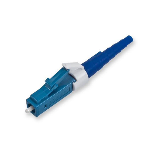
LC male connectors use the familiar RJ style latch found on balanced copper twisted pair plugs and of course are available in singlemode and multimode.
Let's check out some of the advantages:

Numerous application standards recognize the use of simplex and duplex LC style connectors and adapters such as fiber distributed data interface (FDDI), Fibre Channel, broadband integrated services digital network (ISDN), and asynchronous transfer mode (ATM). Gigabit Ethernet also allows the use of SFF connectors.
Need more fiber optic information? Check out other post on our blog and our YouTube Channel.
"By Mercy Salinas"
LC connectors are available in a simplex and duplex arrangement. The simplex connectors are suitable for termination to buffered fiber while maintaining proper bend radius requirements in tight spaces.
Let's take a look at a simplex LC fiber plug before it's terminated.

Here's a look at a duplex LC fiber plug, typically more common with fiber patch jumpers.
LC male connectors use the familiar RJ style latch found on balanced copper twisted pair plugs and of course are available in singlemode and multimode.
Advantages and disadvantages of LC style fiber optic connectors
Let's check out some of the advantages:
- It is available as a simplex connector that can be converted to a duplex connector using a clip.
- It is keyed, low loss, pull proof, and wiggle proof.
- It can be terminated quickly in many different ways, including quick-cure adhesive, cleave and crimp, and hot melt.
- It features SFF design, suitable for high density applications.
- The LC connector and adapters are commonly used in network equipment transceivers.

Numerous application standards recognize the use of simplex and duplex LC style connectors and adapters such as fiber distributed data interface (FDDI), Fibre Channel, broadband integrated services digital network (ISDN), and asynchronous transfer mode (ATM). Gigabit Ethernet also allows the use of SFF connectors.
Need more fiber optic information? Check out other post on our blog and our YouTube Channel.
"By Mercy Salinas"


What are the most popular Fiber Optic Connector types?
When I first started terminating fiber optic connectors around 15 years ago maybe around 1997, I remember doing a handful of different types. Like FC, FDDI, MT Array, SC, ST, SMA, MTRJ, MU and so on. It was a huge chore, not only knowing how to properly terminate all these but having to stock all of these connectors to take care of your customers needs in a timely fashion.
I do remember around the year 2000-2001 the MTRJ connector had an amazing spurt where it felt like the industry was possibly standardizing on a connector but no.
The only connectors that have stood the test of time are the SC and ST connectors. The SC connectors (Set and Click is what I call them) are a square front design while the ST (Set and Twist) connector is round and is basically a smaller version of a coax BNC male connector.
Here's a quick look at one of our YouTube videos on the most common connectors as of today.
The LC connector has really been a beast over the past couple of years. It seems to be a more common input for Hewlett Packard Pro Curve and Cisco Catalyst switches and for SFP modules.
These 3 connectors seem to be the most common at this point in time but there is also another connector called MPO that has been gaining traction in data centers and could possibly contend for popularity in the long term.
Now if your thinking about terminating these connectors check out another one of our many YouTube videos, this one is called How to Terminate Fiber Optic Network Cable
Comment below please. Thanks!
"By Mercy Salinas"
I do remember around the year 2000-2001 the MTRJ connector had an amazing spurt where it felt like the industry was possibly standardizing on a connector but no.
The only connectors that have stood the test of time are the SC and ST connectors. The SC connectors (Set and Click is what I call them) are a square front design while the ST (Set and Twist) connector is round and is basically a smaller version of a coax BNC male connector.
Here's a quick look at one of our YouTube videos on the most common connectors as of today.
The LC connector has really been a beast over the past couple of years. It seems to be a more common input for Hewlett Packard Pro Curve and Cisco Catalyst switches and for SFP modules.
These 3 connectors seem to be the most common at this point in time but there is also another connector called MPO that has been gaining traction in data centers and could possibly contend for popularity in the long term.
Now if your thinking about terminating these connectors check out another one of our many YouTube videos, this one is called How to Terminate Fiber Optic Network Cable
Comment below please. Thanks!
"By Mercy Salinas"
Fiber Optic Cable Cleaver Tool Overview
The CT-10A fiber optic cleaver provides high quality cleaving at an economical price. Designed for cleaving single fiber only, this cleaver is best suited for the installation of field installable connectors and mechanical splices. The rugged yet scaled-down design offer cleave quality approaching that of more expensive high precision cleavers. The long-life, 16-position fat diamond blade is easily replaced by the end user and performs cleaving operation in one single step. An optional scrap collector can be purchased separately.
• Dedicated for single fiber cleaving
• User replaceable flat diamond blade
• Simple and single-step operation
• Blade life up to 64,000 cleaves
• Compact and light weight
• Detachable fiber scrap collector FC-03 available as option
Applicable Fiber: Conventional silica optical fiber
Fiber Count: Single fiber
Coating Diameter: 250µm to 900µm
Cladding Diameter: 125µm
Cleave Length:
6 to 20 mm (with AD-10 & coating = 250µm)
8 to 20mm (with AD-10 & coating > 250µm)
10mm (with FH-50/60 fiber holders)
Cleave Angle: Capability Typically 0.5˚
Dimensions: (W x D x H) 71mm x 88mm x 48mm (2.8" x 3.5" x 1.9")
Weight: 220g (0.48 lbs)
For more information on termination fiber optic cable and connectors you may contact Mercy Salinas at 888-797-3697 extension 232 or comment below!
"Author: Mercy Salinas"
Read more »
• Dedicated for single fiber cleaving
• User replaceable flat diamond blade
• Simple and single-step operation
• Blade life up to 64,000 cleaves
• Compact and light weight
• Detachable fiber scrap collector FC-03 available as option
Applicable Fiber: Conventional silica optical fiber
Fiber Count: Single fiber
Coating Diameter: 250µm to 900µm
Cladding Diameter: 125µm
Cleave Length:
6 to 20 mm (with AD-10 & coating = 250µm)
8 to 20mm (with AD-10 & coating > 250µm)
10mm (with FH-50/60 fiber holders)
Cleave Angle: Capability Typically 0.5˚
Dimensions: (W x D x H) 71mm x 88mm x 48mm (2.8" x 3.5" x 1.9")
Weight: 220g (0.48 lbs)
For more information on termination fiber optic cable and connectors you may contact Mercy Salinas at 888-797-3697 extension 232 or comment below!
"Author: Mercy Salinas"
12 strand fiber optic cable by Corning Cable Systems
As you know Corning has a few different types of 12 strand fiber optic cables. Right now we're going to get to know Corning part number 012K8F-31130-29 much better.
This number is part of the FREEDM ONE design. It's flame retardant, UV resistant and the indoor/outdoor rating allows for aerial, duct and direct burial applications with no need for a transition splice when entering the building.
The tight-buffered construction facilitates easier termination for low fiber count applications in your local area network and eliminates the need for fan out kits. Color coded to the TIA-598 standard for easy identification.
The small diameter and bend radius of the cable also allows for easy installation in space constrained areas while the innovative water blocking technology is ideal for outside plant applications. The all dielectric cable construction requires no grounding or bonding and the jacket is rugged, durable and easy to strip.
Let's get a better look at this cable from our YouTube Channel
Now that you know Corning part number 012K8F-31130-29 is more than a 12 strand, tight buffered, riser rated, 62.5 multimode cable, I think your ready to pull that fiber.
"By Mercy Salinas"
This number is part of the FREEDM ONE design. It's flame retardant, UV resistant and the indoor/outdoor rating allows for aerial, duct and direct burial applications with no need for a transition splice when entering the building.
The tight-buffered construction facilitates easier termination for low fiber count applications in your local area network and eliminates the need for fan out kits. Color coded to the TIA-598 standard for easy identification.
The small diameter and bend radius of the cable also allows for easy installation in space constrained areas while the innovative water blocking technology is ideal for outside plant applications. The all dielectric cable construction requires no grounding or bonding and the jacket is rugged, durable and easy to strip.
Let's get a better look at this cable from our YouTube Channel
Now that you know Corning part number 012K8F-31130-29 is more than a 12 strand, tight buffered, riser rated, 62.5 multimode cable, I think your ready to pull that fiber.
"By Mercy Salinas"
2 strand zip fiber cable for 10 Gigabit Ethernet Speed
Your bulk two strand fiber cable is typically used for certain installation applications, but before we get to that let's check out our OM3 zip cord fiber video.
A two strand zip fiber is most common for installations from your telecom closet to your desk and since this cable is OM3 rated for 10 Gigabit Ethernet you just future-proofed your network!
"By Mercy Salinas"
A two strand zip fiber is most common for installations from your telecom closet to your desk and since this cable is OM3 rated for 10 Gigabit Ethernet you just future-proofed your network!
"By Mercy Salinas"
AFL Fujikura 12S Fiber Optic Fusion Splicer
Finally! A new fusion splicer to brag about, over the past few years fusion splicers have come around but they've all had that boring, bulky and dull nothing to see here feeling to them. The new Fujikura 12S is, kinda sexy.
This new fusion splicer is now the smallest, lightest and most portable splicer in the world! The chassis features shock, dust and moister protection, excellent for those rugged fiber optic cable installations.

The two camera observation system provides for accurate fiber optic alignment and loss estimation calculations.
Weighing less than two pounds and a footprint of 6 inches by 5 inches this provides an awesome level of flexibility in the most demanding splicing environments. The big 4.5 inch monitor is scratch resistant and is viewable in direct sunlight! You can update the software via the internet and I really enjoyed the long battery life, you can get up to 100 splice cycles which include the application of the splice protection sleeve!
Sold in three different ways. You can purchase the 12S fusion splicer without a cleaver. Part number S015521 .

You can also purchase the 12S with a CT-10 cleaver. Part number S015530 .
If your looking for a cleaver that will also do ribbon fiber then you'll want part number S015522 and that includes the top dog cleaver, the CT-30.
All three part numbers include the transit case, screwdriver, battery pack, alcohol container and other items.

It's a real cool fusion splicer and the pricing is excellent. For more information on the 12S Fusion Splicer you can contact Mercy Salinas at 888-797-3697 extension 232. If you have a quick question you can also comment below. Thanks!
"By Mercy Salinas"
Are the new Corning CCH rackmount enclosures that cool?
This year Corning Cable Systems redesigned their popular CCH series 19 inch rack mount fiber optic enclosures. When I first heard this I pictured Bill Lumbergh saying, "I'm just not sure about that right now".

It's already a great design and Corning has probably sold millions of them. When I get a call from a fiber optic installation contractor trying to figure out what brand of enclosure he has at a installation he did 15 years ago it seems to always be the CCH series. Sure they were called Siecor back then but the same CCH panels are used.
Let's take a look at the now older designed CCH-01U from our YouTube Channel .
As you noticed the older design was great, opened easy on the front, rear and top. Slides out easy for your fiber adapter panels to be installed and it had an awesome black powder coat that'll last for a real long time.
Now let's look at the new redesigned CCH-01U from our YouTube Channel .
What I like most about the redesign is the see through top cover. I think seeing into the enclosure without removing a panel is so cool. If you need to remove the top panels the tool-less design makes it easy to remove.
Looks like Corning really outdid themselves with this new redesign, and they're still showing the older CCH-01U rackmount enclosure love by still offering it under a new part number CLSSC-01U.
You can order the CCH-01U from our site and please feel free to comment below.
Thanks
"By Mercy Salinas"
It's already a great design and Corning has probably sold millions of them. When I get a call from a fiber optic installation contractor trying to figure out what brand of enclosure he has at a installation he did 15 years ago it seems to always be the CCH series. Sure they were called Siecor back then but the same CCH panels are used.
Let's take a look at the now older designed CCH-01U from our YouTube Channel .
As you noticed the older design was great, opened easy on the front, rear and top. Slides out easy for your fiber adapter panels to be installed and it had an awesome black powder coat that'll last for a real long time.
Now let's look at the new redesigned CCH-01U from our YouTube Channel .
What I like most about the redesign is the see through top cover. I think seeing into the enclosure without removing a panel is so cool. If you need to remove the top panels the tool-less design makes it easy to remove.
Looks like Corning really outdid themselves with this new redesign, and they're still showing the older CCH-01U rackmount enclosure love by still offering it under a new part number CLSSC-01U.
You can order the CCH-01U from our site and please feel free to comment below.
Thanks
"By Mercy Salinas"
Corning CamSplice mechanical splice tool overview and How To
I just want to talk about this tool by Corning as an easy and effective way to mechanically splice fiber optic cable.
Let's check out some of the features.
* No adhesive or epoxy required
* Reduces splice time with no curing needed
* Universal one part fits all fiber coatings
* No polishing required
* Reduces installation time
* Fiber alignment mechanism
* Self centers the fiber for low loss
Now let's figure out how to splice fiber optic cable.
It's a very simple process and I know you can do it. Just a quick tip, if your repairing a direct burial fiber it's recommended that you replace the cable at least 30 feet in each direction so you'll have to do as least 2 splices per strand of fiber.
"By Mercy Salinas"
Let's check out some of the features.
* No adhesive or epoxy required
* Reduces splice time with no curing needed
* Universal one part fits all fiber coatings
* No polishing required
* Reduces installation time
* Fiber alignment mechanism
* Self centers the fiber for low loss
Now let's figure out how to splice fiber optic cable.
It's a very simple process and I know you can do it. Just a quick tip, if your repairing a direct burial fiber it's recommended that you replace the cable at least 30 feet in each direction so you'll have to do as least 2 splices per strand of fiber.
"By Mercy Salinas"
Copper twisted pair OSP or Fiber Optic outside plant?
With the rise of fiber optic cable networks more people are considering fiber over traditional copper twisted pair communications cable. Let's take a quick look at some of the pros and cons for both.
Balanced twisted pair cable transports information over the cable as an electrical signal. One advantage is it's already installed everywhere on the planet. Twisted pair cables were invented by Alexander Graham Bell in 1881 and is the most popular cable for our communication from one human being to another. This is an old technology but because of it's longevity more people are familiar with it and the installation process.
Here's an example of a OSP telephone cable from our YouTube Channel
There are some things about this cable that can make it a bit of a bummer. High sensitivity to external electromagnetic interference, the most common troublemaker seems to be lightning strikes. OSP copper cable will need to be properly grounded and that by itself is another science that the installation contractor must be knowledgeable about.
High bandwidth applications over twisted pair also has distance limitations. Cat5e can only transmit gigabit ethernet up to 100 meters. T-1 service within a 50 pair cable will be limited to 6 transmit signals in one binder group and 6 receive signals in a second binder group.
The size and weight of the cable will also present more cost in transportation.
Twisted pair cabling has definitely been supporting voice application services for a long time but with new technology and the need for more information faster, fiber optic cabling has been growing to support high bandwidth applications. At this point in time I do see many new installations using a combination of both.
For fiber optic outside plant environments we've sold fiber for voice, video, data, audio, CATV, fire alarms, CCTV and building automation systems. In campus environments it has the ability to sever many different transmission protocols and topologies by offering increased distance, higher bandwidth, all-dielectric cable, less susceptibility to EMI, lightning and no grounding!
Here's an example of a OSP fiber cable from our YouTube Channel
Now that you have something to chew on, take your time and plan your system for things like future growth, longevity, flexibility and so on. You may even need to have a mixed bag of multimode, singlemode and twisted pair.
Don't forget Halo 4 came out this week so pick up a copy and I'll see you on the XBOX live network.

Questions? Comments? Leave them below! Thanks.
"By Mercy Salinas"
Balanced twisted pair cable transports information over the cable as an electrical signal. One advantage is it's already installed everywhere on the planet. Twisted pair cables were invented by Alexander Graham Bell in 1881 and is the most popular cable for our communication from one human being to another. This is an old technology but because of it's longevity more people are familiar with it and the installation process.
Here's an example of a OSP telephone cable from our YouTube Channel
There are some things about this cable that can make it a bit of a bummer. High sensitivity to external electromagnetic interference, the most common troublemaker seems to be lightning strikes. OSP copper cable will need to be properly grounded and that by itself is another science that the installation contractor must be knowledgeable about.
High bandwidth applications over twisted pair also has distance limitations. Cat5e can only transmit gigabit ethernet up to 100 meters. T-1 service within a 50 pair cable will be limited to 6 transmit signals in one binder group and 6 receive signals in a second binder group.
The size and weight of the cable will also present more cost in transportation.
Twisted pair cabling has definitely been supporting voice application services for a long time but with new technology and the need for more information faster, fiber optic cabling has been growing to support high bandwidth applications. At this point in time I do see many new installations using a combination of both.
For fiber optic outside plant environments we've sold fiber for voice, video, data, audio, CATV, fire alarms, CCTV and building automation systems. In campus environments it has the ability to sever many different transmission protocols and topologies by offering increased distance, higher bandwidth, all-dielectric cable, less susceptibility to EMI, lightning and no grounding!
Here's an example of a OSP fiber cable from our YouTube Channel
Now that you have something to chew on, take your time and plan your system for things like future growth, longevity, flexibility and so on. You may even need to have a mixed bag of multimode, singlemode and twisted pair.
Don't forget Halo 4 came out this week so pick up a copy and I'll see you on the XBOX live network.

Questions? Comments? Leave them below! Thanks.
"By Mercy Salinas"
SC Fiber Optic Cable Connector Overview
The SC (Subscriber Connector) style has numerous types of standards recognizing simplex and duplex connectors and adapters. Standards recognizing the SC are FDDI, Fibre Channel, broadband ISDN, ATM and Gigabit Ethernet.

As you can tell the SC fiber optic connector has a square style front face and is easily confused with it's smaller relative the LC connector. Let's take a look at some of the advantages of the SC connector.
- Available as a simplex connector that can be converted to a duplex connector using a clip.
- Recommended by a large number of standards.
- Offers pull-proof feature.
- Great packing density, design reduces the chance of the fiber face damage during connection.
- Keyed, low loss, pull and wiggle proof.
- Terminated using quick cure epoxy, cleave and crimp and hot melt.
Typically what you'll find at a subscribers location is the bulk horizontal or backbone cable side ends it's run in the facilities telecommunications closet. Your SC connectors will then be managed in a fiber optic enclosure. Let's check out one of my favorites by Corning.
Then the information technology manager, will manage his end using fiber optic patch jumpers that plug into an adapter panel that sits in the fiber optic enclosure.
The SC interface is very commonly used when using media converters to convert copper to fiber, then fiber to copper. The big disadvantage of the SC interface is it does not feature an SFF (Small Form Factor) design.
The SFF design commonly uses the LC interface, so if you have an application where the backbone cable needs to be plugged directly into a switch the LC connector will be required. It's still recommended that you use a fiber enclosure, you could just get a fiber jumper with SC on one end and the LC on the other.
"By Mercy Salinas"
GPON, what is it and why install it?
A Gigabit Passive Optical Network (GPON) is a point-to-multipoint, fiber to the premises network architecture in which unpowered optical splitters are used to enable a single strand of fiber to serve multiple premises, typically 16 to 128. A PON consists of an optical line terminal at the service provider's central office and a number of optical fiber network units near end users. A PON reduces the amount of fiber and central office equipment required compared with point-to-point architectures. A passive optical network is a form of fiber-optic access network.

Downstream signals are broadcast to all premises sharing multiple fibers. Encryption can prevent eavesdropping.
Let's take a quick look at why you'd install GPON. This Tellabs Passive Optical LAN video using GPON technology at the Department of Energy Sandia Lab in New Mexico gives us a good feel for the benefits.
Looks like it's time to redesign the network again. Maybe for the last time.
"By Mercy Salinas"

Downstream signals are broadcast to all premises sharing multiple fibers. Encryption can prevent eavesdropping.
Let's take a quick look at why you'd install GPON. This Tellabs Passive Optical LAN video using GPON technology at the Department of Energy Sandia Lab in New Mexico gives us a good feel for the benefits.
Looks like it's time to redesign the network again. Maybe for the last time.
"By Mercy Salinas"
Fiber Optic Cable for a Wind Farm? What cable to use?
Recently we've been been moving fiber optic cables into the green energy market and in a previous post we got into it regarding Solar Power Towers . The long term view from the US department of Energy is a commitment to renewable energy, so not only will you see the expansion of these solar power towers but also wind farms.

Are wind farms a new thing? No, the San Gorgonio Pass Wind Farm development began in the early 80's. You figured a standardized fiber optic cable type by now would have been established but it doesn't appear that way. I looked into Corning, AFL and General Cable and I don't see any type of fiber optic cable designed for this specific application.
So what fiber cable is going to be a good fit for your wind farm application? I'm going to put money down on a tight buffered indoor/outdoor cable.
Why not! The majority of the cable is not exposed externally, cable runs from the top in the pole to the base then runs underground with other cables. The most commonly installed cable for cell tower applications is the indoor/outdoor tight buffered construction. Because it runs vertically you don't want a loose tube and since it has no aluminum, copper or any metal your don't have to worry about interference from the electrical cables from the wind farm.
The data rates look to be 10/100 so a 62.5 multimode cable will cover you up to around 2 kilometers, anything over that singlemode get's involved. I don't think the fiber cable should be a complicated part of this type of installation. Fiber cable from a cell tower, data center, home, wind farm all does the same thing by getting a signal from point A to B.
I'm going to work on getting my foot in the door at the San Gorgonio Pass Wind Farm since they're right down the street from me, I could be wrong and maybe it's a completely different cable. I'll work on verifying the cable that's being installed and if you work at a wind farm please comment! It'll be much appreciated.
"By Mercy Salinas"

Are wind farms a new thing? No, the San Gorgonio Pass Wind Farm development began in the early 80's. You figured a standardized fiber optic cable type by now would have been established but it doesn't appear that way. I looked into Corning, AFL and General Cable and I don't see any type of fiber optic cable designed for this specific application.
So what fiber cable is going to be a good fit for your wind farm application? I'm going to put money down on a tight buffered indoor/outdoor cable.
Why not! The majority of the cable is not exposed externally, cable runs from the top in the pole to the base then runs underground with other cables. The most commonly installed cable for cell tower applications is the indoor/outdoor tight buffered construction. Because it runs vertically you don't want a loose tube and since it has no aluminum, copper or any metal your don't have to worry about interference from the electrical cables from the wind farm.
The data rates look to be 10/100 so a 62.5 multimode cable will cover you up to around 2 kilometers, anything over that singlemode get's involved. I don't think the fiber cable should be a complicated part of this type of installation. Fiber cable from a cell tower, data center, home, wind farm all does the same thing by getting a signal from point A to B.
I'm going to work on getting my foot in the door at the San Gorgonio Pass Wind Farm since they're right down the street from me, I could be wrong and maybe it's a completely different cable. I'll work on verifying the cable that's being installed and if you work at a wind farm please comment! It'll be much appreciated.
"By Mercy Salinas"
Mine Safety and Health Administration Approved Fiber Cable
Today's mining engineers are heavily relied on to plan mining operations. From designing underground and surface mines to equipment and even supervising the operators who run it.

Because of the high demands from not only the job site but from the Mine Safety and Health Administration the importance of a MSHA approved cable is greater then ever.
Discount-Low-Voltage.com offers a MSHA approved cable from AFL Telecommunications. The outer jacket is manufactured with a UV stabilizer for protection against exposure to the sun plus anti-fungus protection for use in underground applications.
This Fiber cable is also water blocked and meets water penetration requirement of GR-20-CORE. (This helps ensure that any damage to the cable is restricted to a repairable length of several meters.) Includes a riser rating so cable can be used in all environments, general inside plant and outside plant. Tested to meet or exceed EIA/TIA 568-A, GR-409-CORE and ICEA-S-104-696. Compliant to directive 202/95/EC RoSH.
Cable is cut to length to whatever your requirement might be, 625 feet or 8,750 feet and a continuous run is no problem. You may also consider our preterminated option so you can provide a plug and play solution at the mine.
Questions? You may contact Mercy Salinas at 888-797-3697 extension 232.
"By Mercy Salinas"

Because of the high demands from not only the job site but from the Mine Safety and Health Administration the importance of a MSHA approved cable is greater then ever.
Discount-Low-Voltage.com offers a MSHA approved cable from AFL Telecommunications. The outer jacket is manufactured with a UV stabilizer for protection against exposure to the sun plus anti-fungus protection for use in underground applications.
This Fiber cable is also water blocked and meets water penetration requirement of GR-20-CORE. (This helps ensure that any damage to the cable is restricted to a repairable length of several meters.) Includes a riser rating so cable can be used in all environments, general inside plant and outside plant. Tested to meet or exceed EIA/TIA 568-A, GR-409-CORE and ICEA-S-104-696. Compliant to directive 202/95/EC RoSH.
Cable is cut to length to whatever your requirement might be, 625 feet or 8,750 feet and a continuous run is no problem. You may also consider our preterminated option so you can provide a plug and play solution at the mine.
Questions? You may contact Mercy Salinas at 888-797-3697 extension 232.
"By Mercy Salinas"
What is and why do I need a fiber optic mandrel?
Over the past 15 years we've sold all kinds of fiber products for all kinds of different projects but I think the most overlooked part about a fiber optic network installation might be the use of fiber optic mandrels for proper insertion loss testing.
Before we get into the mandrels themselves let's all get on the same page with "ZEROING" your fiber optic light source and power meter. Our good friend Professor Jim Powers with Optical Wavelength Laboratories gives us a great explanation on "ZEROING".
Thanks Professor Jim Powers, now let's get into the mandrel.
Your LED light source emits light over an area larger than the typical multimode fiber core causing the low and high order modes to get excited. The simplest way to calm your light source down is to tightly bend the launch cable from your light source tester around a mandrel.
A fiber optic mandrel is a very inexpensive tool to help improve your fiber optic testing as the tight bends around the mandrel calm the light source down. Mandrels allow the use of your overfilled LED light source to properly certify 50 and 62.5 fiber links for high bit rates such as Gigabit Ethernet and 10 Gigabit Etherent.
Here's a up close look from our YouTube channel
These mandrels are not a "want to" or "don't want to" tool to use during testing. This is not 'Nam, there are rules, and according to TIA/EIA-568-B it specifies that attenuation (insertion loss) measurements of multimode fiber links for all applications be made using an overfilled light source, such as an LED with a mandrel-wrap mode filter on the transmit jumper. This enables certification of multimode links for Gigabit and 10 Gigibit. Also allows for existing 850/1300 LED light sources to test 50 and 62.5 links.
Now let's use our fiber mandrel for "ZEROING"!
Wrap the "transmit jumper" five times around the mandrel and attach it to the output port of your LED source. Then attach the other end of the jumper to your power meter and set your wavelength.

Set your reference to display "0 dB" indicating that the power measured at output of the transmit jumper has been recorded as the reference level for your insertion loss measurements. You have now completed the "One Jumper Method".
Now disconnect your transmit jumper from your power source but NOT from your light source. Attach a "receive jumper" to to your power meter. Mate together the "transmit jumper" and "receive jumper" with a coupler. Make sure that the insertion loss is well under 0.75 dB and that is the maximum allowed by TIA.

Now your ready to test the fiber link. Connect your light source to one end and your power meter to the other. Store results, print and rock and roll!

So long story short, a fiber mandrel is for modifying the distribution of a propagating fiber optic signal. You can order your fiber optic mandrel from DLV.
Questions? Comment below, thanks!
"By Mercy Salinas"
Before we get into the mandrels themselves let's all get on the same page with "ZEROING" your fiber optic light source and power meter. Our good friend Professor Jim Powers with Optical Wavelength Laboratories gives us a great explanation on "ZEROING".
Thanks Professor Jim Powers, now let's get into the mandrel.
Your LED light source emits light over an area larger than the typical multimode fiber core causing the low and high order modes to get excited. The simplest way to calm your light source down is to tightly bend the launch cable from your light source tester around a mandrel.
A fiber optic mandrel is a very inexpensive tool to help improve your fiber optic testing as the tight bends around the mandrel calm the light source down. Mandrels allow the use of your overfilled LED light source to properly certify 50 and 62.5 fiber links for high bit rates such as Gigabit Ethernet and 10 Gigabit Etherent.
Here's a up close look from our YouTube channel
These mandrels are not a "want to" or "don't want to" tool to use during testing. This is not 'Nam, there are rules, and according to TIA/EIA-568-B it specifies that attenuation (insertion loss) measurements of multimode fiber links for all applications be made using an overfilled light source, such as an LED with a mandrel-wrap mode filter on the transmit jumper. This enables certification of multimode links for Gigabit and 10 Gigibit. Also allows for existing 850/1300 LED light sources to test 50 and 62.5 links.
Now let's use our fiber mandrel for "ZEROING"!
Wrap the "transmit jumper" five times around the mandrel and attach it to the output port of your LED source. Then attach the other end of the jumper to your power meter and set your wavelength.

Set your reference to display "0 dB" indicating that the power measured at output of the transmit jumper has been recorded as the reference level for your insertion loss measurements. You have now completed the "One Jumper Method".
Now disconnect your transmit jumper from your power source but NOT from your light source. Attach a "receive jumper" to to your power meter. Mate together the "transmit jumper" and "receive jumper" with a coupler. Make sure that the insertion loss is well under 0.75 dB and that is the maximum allowed by TIA.

Now your ready to test the fiber link. Connect your light source to one end and your power meter to the other. Store results, print and rock and roll!

So long story short, a fiber mandrel is for modifying the distribution of a propagating fiber optic signal. You can order your fiber optic mandrel from DLV.
Questions? Comment below, thanks!
"By Mercy Salinas"
Running fiber to the antenna (FTTA)? Need help?
Contractors are realizing that fiber optic fed architectures are rapidly becoming the new norm for new tower builds and retrofits. This fiber solution is viewed by the industry as the best solution to support current demand, save energy and leave a smaller footprint.
Why now? This transition from traditional coax cables to fiber has been pushed by radio cell sizes becoming smaller due to increasing data rates, higher transmission frequencies and increased volume of data. In the figure below notice how the GSM system is at a lower frequency and new systems operate at a higher frequency.
With new systems like 4G the propagation losses increases with the square of the frequency, meaning that smaller radio cells are needed for equivalent network coverage. Number of antennas and base stations now increase.
Now that more and more antennas are being installed the traditional coaxial cable system has its limitations. These cables are limited to less than fifty meters and are very prone to losses that can hurt cell phone coverage. With a FTTA installation the electronics are taken from the base and are located at a remote radio head (RRH) by the antenna then is linked to the base using fiber cable. Your typical data rates are one Gigabit per second base to remote radio head.
Network operators also view FTTA as an excellent way to reduce capital and operating expenditures.
* Less or no additional space required for installation
* Less power provision and lower power amplification required
* Lower acquisition cost
* Simple system install
* Up to 40% less power consumption
* Lower rental cost of telecom and antenna cost
The most common way to install your fiber optic cable is to home run the cable. Many installations will use a pre-terminated solution saving on installation time and labor.
Next to the RRH Corning has a product called a remote radio distribution terminal that allows you to keep not only the signal but also the power organized in a clean weatherproof rated environment.
At the base your traditional 19 inch rack mountable enclosure can be used to hold your fiber cable.
If your looking for durability you might also consider a environmental distribution center as a demarcation point.
Now that you have a better understanding of the need for FTTA and what materials are used don't forget to recycle that old coaxial cable.
Please comment if you have any questions or you may contact Mercy Salinas at 888-797-3697 extension 232.
"By Mercy Salinas"
Why now? This transition from traditional coax cables to fiber has been pushed by radio cell sizes becoming smaller due to increasing data rates, higher transmission frequencies and increased volume of data. In the figure below notice how the GSM system is at a lower frequency and new systems operate at a higher frequency.
With new systems like 4G the propagation losses increases with the square of the frequency, meaning that smaller radio cells are needed for equivalent network coverage. Number of antennas and base stations now increase.
Now that more and more antennas are being installed the traditional coaxial cable system has its limitations. These cables are limited to less than fifty meters and are very prone to losses that can hurt cell phone coverage. With a FTTA installation the electronics are taken from the base and are located at a remote radio head (RRH) by the antenna then is linked to the base using fiber cable. Your typical data rates are one Gigabit per second base to remote radio head.
Network operators also view FTTA as an excellent way to reduce capital and operating expenditures.
* Less or no additional space required for installation
* Less power provision and lower power amplification required
* Lower acquisition cost
* Simple system install
* Up to 40% less power consumption
* Lower rental cost of telecom and antenna cost
The most common way to install your fiber optic cable is to home run the cable. Many installations will use a pre-terminated solution saving on installation time and labor.
Next to the RRH Corning has a product called a remote radio distribution terminal that allows you to keep not only the signal but also the power organized in a clean weatherproof rated environment.
At the base your traditional 19 inch rack mountable enclosure can be used to hold your fiber cable.
If your looking for durability you might also consider a environmental distribution center as a demarcation point.
Now that you have a better understanding of the need for FTTA and what materials are used don't forget to recycle that old coaxial cable.
Please comment if you have any questions or you may contact Mercy Salinas at 888-797-3697 extension 232.
"By Mercy Salinas"
Easy way to clean ST, SC fiber connectors and adapters
One of the most over looked part of a fiber optic network installation is the cleaning. I know it's one of the smallest parts of the overall install, it's inexpensive and not sexy but what do the facts say about fiber optic cleaning.
• Proper cleaning saves money – by eliminating service calls caused by dirty connectors
• Clean connectors maximize the performance of the network and reduce repair cost
• Proper cleaning extends the life of connects and reduces replacement costs
• Dirty connectors cause a major percentage of fiber optic network failures
• Prevention is simple – Clean Connectors!
• Cleaning Saves Time and Money!
For keeping your connectors and adapters clean you have several options available and you might be asking yourself what's my best option? That question seems to be an installer preference but one of those preferences that network professionals commonly use is the AFL one click cleaner.
The AFL one click cleaner is designed to be extremely easy to use for connectors, patch jumpers and adapters. Simply push the cleaner until a click is heard. Your push sends a fiber optic grade cleaning tape into action ensuring your fiber optic end face is effectively and gently cleaned. Excellent choice for field technicians and small enough to fit in your shirt pocket.
Questions? Contact Mercy Salinas at 888-797-3697 extension 232.
"By Mercy Salinas"
Read more »
• Proper cleaning saves money – by eliminating service calls caused by dirty connectors
• Clean connectors maximize the performance of the network and reduce repair cost
• Proper cleaning extends the life of connects and reduces replacement costs
• Dirty connectors cause a major percentage of fiber optic network failures
• Prevention is simple – Clean Connectors!
• Cleaning Saves Time and Money!
For keeping your connectors and adapters clean you have several options available and you might be asking yourself what's my best option? That question seems to be an installer preference but one of those preferences that network professionals commonly use is the AFL one click cleaner.
The AFL one click cleaner is designed to be extremely easy to use for connectors, patch jumpers and adapters. Simply push the cleaner until a click is heard. Your push sends a fiber optic grade cleaning tape into action ensuring your fiber optic end face is effectively and gently cleaned. Excellent choice for field technicians and small enough to fit in your shirt pocket.
Questions? Contact Mercy Salinas at 888-797-3697 extension 232.
"By Mercy Salinas"
Subscribe to:
Posts (Atom)