Showing posts with label How To. Show all posts
Showing posts with label How To. Show all posts
Friday, December 4, 2015
How To Add C Wire To Thermostat
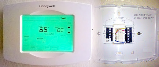
The thermostat I was replacing only controls my gas fired, hot water boiler which provides heat only. I didn't have to worry about cooling as my AC unit runs off a separate thermostat. There were three wires coming out of the wall where my old thermostat was mounted. My heating system only requires two wires, R and W, to operate. I thought I could use the third wire to power my thermostat and use that as the C wire. Unfortunately I ran into a couple of problems.
First, there wiring was very old and there appeared to be a break in that third wire. I couldn't get current to flow to it from the basement.
Second, and probably most importantly, I called the manufacturer of my boiler to double check that it would be okay to connect the thermostat to the C terminal on the 24 volt AC transformer in the boiler. These types of thermostats are called "power stealing" thermostats and the manufacturer (Weil McLain) does not recommend using a power stealing thermostat with my boiler. They were worried that the additional load from the thermostat may cause the transformer to prematurely burn out. They recommend using a separate 24 vac transformer to power the thermostat.
The instructions for the Honeywell Wi-Fi Programmable Touchscreen Thermostat (RTH8580WF1007/U)
 I was installing didn't specify how to hook up an external power supply to the thermostat but calling customer service I was able to find out how to attach an external transformer. If your thermostat is also controlling your cooling system or you have a different type of heating system the configuration might be different. It's a good idea to call the manufacturer of your thermostat and get specific instructions for your model and HVAC unit.
Update: wi-fi on the thermostat sucks. You can only update the thermostat provided the thermostat can connect to the internet. Hurricane Sandy caused me to lose my home internet but I still had power and heat. When I went to bed the following night I was chilled do the bone having been outside most of the day dealing with the aftermath and i wanted to turn up the heat without getting out of bed but i couldn't because my internet was down. I could access all other wired and wireless devices on my network, just no internet access. There is no way to connect to the thermostat directly. It is all done through Honeywell's cloud service which it turns out collects my homes temperature readings and heating system information every 12 seconds. I don't like that and i don't like not being able to access the thermostat from home when my internet is down.
Change Your Thermostat Before It Gets Cold
With any project things can go wrong. You don't want to be in a position where it's the coldest part of winter and you're without heat for whatever reason!
Also check with your HVAC system manufacturer and thermostat manufacturer for specifics about your installation. Check with all applicable local building codes.
If snaking wire through walls and making electrical connections is not something you're comfortable with call an electrician.
What You'll Need
Materials
- New Thermostat (I used a Honeywell RTH8580WF)
- 24 Volt AC plug-in transformer (I used an MGT-2440
)
- 18 gauge thermostat wire. Number of conductors should be at least the amount of wires coming up from your HVAC system + 2 for the transformer. I needed a total of 4 conductors so I purchased the Southwire 50 ft. 18/2-Gauge Thermostat Wire 64162179
. You may need more or less depending on how far you have to run the wire.
- 4 Wire nuts (one for each conductor you'll be using). Small ones, yellow or orange should do it.
- Fire Block Sealant
- Electrical tape.
Tools
- Needle nose pliers with wire cutter
- Wire stripper (if you're not comfortable stripping wire with a wire cutter)
- Philips head screwdriver
- Precision flat-head screwdriver (Like from the Stanley 66-039 6-Piece Jewelers Precision Screwdriver Set
)
- Fish Tape (I used Gardner Bender EFT-21PN 25-Foot Cable Snake Steel Fish Tape
)
- Caulking Gun
Step 1: Plan Your Wiring
I could have continued to use the 2 thermostat wires that were in my wall plus add 2 more wires that will run outside the wall to a nearby outlet where I would plug in the 24vac transformer. I didn't like this setup because I didn't want the wire to the transformer exposed where the thermostat was mounted. The installation would look much cleaner if all the wiring ran through the wall as it did previously.I needed 4 conductors. Two from the boiler and 2 from the 24vac transformer. The closest wire I could find was 5 conductor thermostat wire which is what I used. I was going to run the 5 conductor wire from my thermostat down to my basement and then I'd splice 2 more cables in the basement. One set of 2 conductors going to the boiler and two more going to the transformer which will be plugged into a wall. I used the same 5 conductor wire throughout (except for the connection between the boiler and new wire where I used the existing 3 conductor wire).

There is no standard color coding for thermostat wiring. I decided to use the following convention. R - Red, W - White, Rc - Yellow, C - Blue. The yellow and blue wires will go to the transformer and since it's an AC transformer they could be switched.
The 5 conductor wire will be snaked down the wall into my basement. From there I'll separate it into two runs. The Red and White will connect to an existing wire in my basement that goes into my boiler and connects to the R and W terminals on my boiler. The Yellow and Blue wires will run along another wire that goes to the plug-in 24vac transformer that will be plugged into a nearby outlet in the basement.
Step 2: Turn Off Your HVAC System
Before doing anything turn off the power to your HVAC system. This will vary by system but there should be some sort of switch near your system or there might be a breaker specifically labeled in your main circuit breaker panel.Step 3: Remove Old Thermostat
Your new thermostat will come with instructions and wire labels. Follow the instructions to label your existing wires with the stickers so you know which wire is which.
After you label your wires but before you completely disconnect them from the old thermostat, wrap a pencil around the existing wires and/or tape the wires to the wall the prevent them from slipping down into the hole.
If you need to drill holes for new wall anchors to screw in your new thermostat, do that now. Luckily I was replacing a different Honeywell Programmable thermostat that used the same hole spacing.
Step 4: Run New Thermostat Wire
This is the tricky part and how you run your wire is going to depend on how your existing wire is run. I was lucky and my thermostat had a straight run down the wall it was installed on down to my basement. By pulling on the wire from upstairs and down in the basement I was able to tell that the wire was not firmly stapled to the wall and I'd be able to pull it right out. The types of fasteners I saw used in the basement were fairly loose fitting. If that's not the case for you you might have a harder time snaking the new wire. You might have to make small holes in your walls here or there. Fishing wire can be tricky and you might want to hire an electrician to do this for you. Remember, it's best not to try and tackle this when it's very cold and you don't want to be without heat for a couple of days if something goes wrong.
Prepare Fish Tape
The first time I ever used the GB Fish Tape it was very difficult to get it out of the reel. You're supposed to pull the steel tape out by hand. It's coated in oil which makes it tricky. I took the tape outdoors, don't do this on carpet or the oil will stain it, and pulled out as much of the tape as I could by hand. Then I stepped on the end and pulled on the reel slowly working all the tape out. As my reach wasn't sufficient I walked down the tape to change where I was putting pressure. Be careful not to severely bend the steel tape when doing this. One I got all the tape out I reeled it in and repeated the processes. Now whenever I use the fish tape it comes out effortlessly.
Attach Wire to Fish Tape
From upstairs, where the old wire was coming out of the hole in the wall I attached the wire to the end of the fish tape. There's a small hole in the end that I passed the wires through and then used electrical tape to secure everything together. Make sure that the tape is put on neatly so that the point of connection isn't significantly thicker than the thickness of the wire. Tug on it a few times to make sure the wire isn't going to come off of the fish tape while you're pulling it through the wall.
Make sure you have enough fish tape unreeled to reach down to the other end of the opening.
Pull Wire Down
Next I went down to my basement where the old thermostat wire was coming out of the floor boards. I carefully pulled down on the old wire until the fish tape came down to a working level. I had to run up once to feed in the fish tape when it seemed to get a big snagged. This operation is easier if you have one person guiding the tape down from above and another pulling from below but is doable with one person.
Attach New Wire To Fish Tape

First I unspooled a sufficient length of wire and straightened it out a bit. I made sure to unspool enough wire that when I pulled the end upstairs the spool will still be on the ground so that the weight of the spool wouldn't pull the wire back down.
I stripped off about 1.5" of the brown outer wire wrap exposing the 5 individual colored wires. I passed those wires through the holes in the end of the fish tape. Then I took 3 of the individual strands one by one and wrapped them around the tip of the fish tape. Two in one direction and the other in the other direction. This will help secure the wires on the tape. Finally I securely wrapped the connection using electrical tape and tugged on it a few times to make sure it wouldn't come apart while pulling the wire through the wall.
I had taken a picture before I wrapped the connection with electrical tape to show you how I fastened the wire to the end of the tape. Unfortunately I didn't realize the photo didn't come out when I took it. The description above will hopefully be sufficient. Any way you attach it it's important that it provides some security and doesn't add much to the width.
Pull New Wire Up Through Wall
The first step is to start feeding the wire up from below until the connection between the fish tape and thermostat wire is past the hole. This is one of the points where the wire might snag. It's easier to do this with two people but I managed on my own.
Once the connection was through I double checked that the wire was straight and that there was enough unspooled.
Then I went upstairs and carefully pulled the fish tape up until the new wire came out of the hole in the wall.

I made sure I had enough wire to work with and I wrapped some tape around the new wire, while keeping the tape on the spool, to prevent the wire from slipping back down the hole. You could also wrap the wires around something like a pencil.

Step 5: Connect Wires to Thermostat Base Plate
With the new wire fished through the wall it was time to start wiring up the new thermostat. I trimmed the wire to an appropriate length so about 4 inches was sticking out of the wall. I'd deal with the mess of unwrapping the electrical tape off the end and fish tape later. I began by stripping a couple of inches of the brown outer wire sheath to expose the 5 individual color coded wires within. Then I wrapped the Green wire back against the main wire bundle since I wasn't going to be using it then I stripped about 3/8" off the end of the 4 remaining wires as shown.

Remove Jumper
The base plate of the thermostat comes with a metal jumper connected between Rc and R, it looks like a small staple. This jumper needs to be removed to be able to wire the thermostat to an independent power transformer. To remove it, use the small flat-headed precision screwdriver to loosen the two screws for Rc and R in the black terminal block. You don't need to unscrew them all the way, just until the tops of the screws are flush with the top of the black terminal block. Once both screws are loosened just pull the jumper out.
The Rc terminal is used for connecting the cooling relay. If your thermostat controls both your heating and cooling system I'm not sure how you'd go about wiring an external transformer. In that case you'd likely need to wire your thermostat's C wire directly to the transformer on your 24 volt HVAC system.
Attach Wires
One by one feed the end of each wire into it's appropriate terminal block and screw it down to hold it in place. The convention I'm using is:
- R - Red (to boiler)
- W - White (to boiler)
- Rc - Yellow (to transformer)
- C - Blue (to transformer)
Once the wires are attached you can secure the base plate to the wall. I used a small level on the side to make sure the base was mounted straight. (The top of the thermostat and base plate are curved.) The picture, didn't come out quite as straight :) but you can see how the 4 wires attach to the thermostat's base plate.

Depending on your HVAC system your wiring might be different.
Step 6: Connect Thermostat To Transformer
 Back down in the basement and I ran the new wire to where the connection point to the wiring that goes to the furnace is. I think when they installed my new boiler they spliced in a new thermostat wire into the old one and the connection point is on a wall above the boiler. I ran the new wire to that point, gave my self a little extra to work with in case there where any mistakes and I cut the wire and stapled it securely to the wall.
 I then stripped off about 2" of the brown outer wire sheath. As before I wrapped the green wire back around the main wire since I wasn't going to be using it. Then I stripped off about 3/4" from the ends of the 4 remaining wires.
Next I determined where I was going to plug the 24 vac transformer in and measured out the appropriate length of wire from the spool. I knew I was going to have extra thermostat wire left over and I will be using that instead of getting a different 2 conductor wire since I won't need all 5 for this run.
After trimming the wire to length, I stripped off the ends of the wires and, wrapped the each around one of the 2 screw terminals on the transformer and tightened them down. The position of these two wires isn't important as this is an AC transformer. I picked this particular 24vac transformer (MGT2440) because it had the screw terminals.
Next I attached the yellow wire coming from the transformer to the yellow wire running down from the thermostat. I stripped the ends of both about 3/4", used pliers to wrap the wires around each other in a clockwise direction and secured them with an orange wire nut. I repeated the process for the blue wire from the transformer to the thermostat wire.
Before going any further I wanted to make sure the thermostat was getting power so I plugged the transformer in, ran upstairs, pushed the thermostat onto it's base and was happy to see the screen on :)

I had already configured to wireless settings when I was testing the 24vac transformer before I went through all this trouble.
Step 7: Connect Thermostat to Boiler
There was a 3 conductor wire running from the boiler to the old wiring for the thermostat. Luckily this new wiring was color coded so I knew which colors went to the R and W terminals on the boiler. One by one I attached the Red wire from the new wire that I ran from the thermostat to the basement by stripping off 3/4" off the new wire and wrapping it around the wire running to the thermostat R terminal in the boiler. The boiler wire was previously connected to the old wire and already stripped. I capped the connection with a wire nut and repeated the process for the White wire to the wire that runs to the W terminal on the boiler.
I flipped the switch to turn the power to the boiler back on and ran upstairs to make sure everything was working. I turned up the thermostat and checked to make sure the boiler fired up. While downstairs next to the boiler I used my phone to turn the thermostat down and within a few seconds the boiler turned off. :)
Step 8: Wrap Things Up
Now that I know everything is working correctly I wrapped electrical tape around the wire nuts to help keep them secure and I used the Fire Block Caulking in the opening from the basement up to the wall where the new thermostat wire runs. To be on the safe side I double checked that everything was working. Using the app on my phone I can adjust the thermostat from anywhere.
One of the nice things about having the thermostat plugged into the wall is that the light on the thermostat can always stay on and I don't have to worry about batteries draining. The thermostat is next to an opening I tend to bump into when I go down to grab a glass of water in the middle of the night. Hopefully no more stubbed toes and I never have to worry about replacing the batteries.

How To Make Square Cuts In Dimensional Lumber

There are a number of different ways that you can make square cuts in dimensional lumber such as 1x6's, 2x4, 2x6's, etc., which vary in price. Most will also allow you to make accurate angled cuts such as 45 degree cuts.
As with any tools, make sure to read, understand and follow all instructions that come with the tools.
Good
Speed Square and Circular Saw

The cheapest and quickest way to make square cuts in dimensional lumber if you already have a circular saw is to use a Swanson Speed Square as a saw guide.
Simply place the edge of the square on an edge perpendicular to the direction you'd like to cut and use the edge of the square as a guide to run the edge of your circular saw's fence on.

It's important to follow the guide carefully and to have a good circular saw that will sit flat on it's base and can be adjusted to a true 90 degrees. I have a cheap circular saw that I bought for around $40 that was used for some demolition. I'm not sure if it ever sat flat or was able to get the blade square but it's difficult to get it to now.
If you're using this method do a test cut to make sure the cuts are coming out square. You can use the speed square to measure the angle of the cut.
as a saw guide.Simply place the edge of the square on an edge perpendicular to the direction you'd like to cut and use the edge of the square as a guide to run the edge of your circular saw's fence on.

It's important to follow the guide carefully and to have a good circular saw that will sit flat on it's base and can be adjusted to a true 90 degrees. I have a cheap circular saw that I bought for around $40 that was used for some demolition. I'm not sure if it ever sat flat or was able to get the blade square but it's difficult to get it to now.
If you're using this method do a test cut to make sure the cuts are coming out square. You can use the speed square to measure the angle of the cut.
Better
Miter Box

A miter box is a plastic box that has slits cut at precise angles that guide the saw to allow you to make fairly accurate angled cuts in molding or dimensional lumber. Years ago you could find affordable wooden miter boxes but these days all I see are the plastic ones like the Stanley 20-600 Clamping Miter Box pictured left which includes slits for a number of different angles, including face angles. It comes with a sharp back saw and cam pins to help hold your wood in place. The pins don't hold the wood that securely so some quick clamps
 would help.
pictured left which includes slits for a number of different angles, including face angles. It comes with a sharp back saw and cam pins to help hold your wood in place. The pins don't hold the wood that securely so some quick clamps would help.Contractor Miter Box

The Stanley 20-800 Contractor Grade Clamping Mitre Box is similar to a Jorgensen miter saw I own. The Stanley has holes for cam pins but it's essentially the same. These are slightly more expensive than the yellow plastic miter boxes but are easier to mount on a work bench. The saw has a replaceable blade (click here for replacement blade
 ) which makes it a little cheaper to own in the long run compared to buying an entire back saw
 . The hardened steel saw blade is also capable of cutting metal. If you need to make straight or angle cuts in metal, this is the best manual miter box to buy.
It may look like you can create almost any angle you'd like but it only will lock in on 5 detents for 90, 45 and 22.5 degreens (on either side). It is very affordable compared to power miter saws and provides accurate cuts. The saw blade is very sharp.
I find it easier to use some Quick-Clamps to hold the wood in place rather than the built in clamps.

If you like the idea of a manual miter saw that is safer, cleaner and quieter than a power miter saw but want something a little better you can have a look at the Nobex Proman Miter Saw .
.
is similar to a Jorgensen miter saw I own. The Stanley has holes for cam pins but it's essentially the same. These are slightly more expensive than the yellow plastic miter boxes but are easier to mount on a work bench. The saw has a replaceable blade (click here for replacement blade) which makes it a little cheaper to own in the long run compared to buying an entire back saw. The hardened steel saw blade is also capable of cutting metal. If you need to make straight or angle cuts in metal, this is the best manual miter box to buy.It may look like you can create almost any angle you'd like but it only will lock in on 5 detents for 90, 45 and 22.5 degreens (on either side). It is very affordable compared to power miter saws and provides accurate cuts. The saw blade is very sharp.
I find it easier to use some Quick-Clamps to hold the wood in place rather than the built in clamps.

If you like the idea of a manual miter saw that is safer, cleaner and quieter than a power miter saw but want something a little better you can have a look at the Nobex Proman Miter Saw
.Best
Power Miter Saw

A power miter saw like the Hitachi C10FCE2 10-Inch Compound Miter Saw is almost 4x as much as the contractor miter box but if you have a lot of square or angled cuts to make will be worth the price.
It's noisier than a manual miter box and sawdust gets everywhere but it cuts even hardwood in about a second and with little effort. Compound miter saws are adjustable in 2 different directions and have more flexibility when it comes to angles. There are detents for the more popular angles but you can also usually lock them into any angle you'd like.
If you have a lot of cuts to make but don't want to spend over $100 you can look for a Factory-Reconditioned Ryobi ZRTS1141L 9 Amp 7-1/4-in Miter Saw with Laser or rent one for the day.
is almost 4x as much as the contractor miter box but if you have a lot of square or angled cuts to make will be worth the price.It's noisier than a manual miter box and sawdust gets everywhere but it cuts even hardwood in about a second and with little effort. Compound miter saws are adjustable in 2 different directions and have more flexibility when it comes to angles. There are detents for the more popular angles but you can also usually lock them into any angle you'd like.
If you have a lot of cuts to make but don't want to spend over $100 you can look for a Factory-Reconditioned Ryobi ZRTS1141L 9 Amp 7-1/4-in Miter Saw with Laser
or rent one for the day.How To Find Underground Wires & Valves Using Greenlee 521A

Contents:
1) Headset
2) Ground Stake
3) Transmitter
4) Receiver
5) Carrying Case
6) Black Lead
7) Red Lead
8) Selector Knob
9) ON/OFF Switch
10) Battery Cover
Batteries (included)
• Transmitter: Qty 8 - "D" batteries
• Receiver: Qty 1 - 9v alkaline battery
Note: The transmitter produces high voltage. Turn the transmitter off before handling the output leads. Disconnect all wires from the controller when fault locating. Turn the selector knob to the BATTERY TEST position. The meter should read between 8 and 10.
Before starting, you must ensure the transmitter is set up properly.
IMPORTANT: To ensure that the 521A transmitter is producing optimum signal, connect the red and black leads together and turn the unit on. Turn the selector knob to position #5. The meter needle should rise to at least a 10 reading.
1. With the transmitter off, connect the red lead to the wire to be located and the black lead to a good earth ground with the stake provided. (Refer to Figure 1). If the clock is indoors, the earth ground stake MUST be grounded at the point where the wires exit the building. It might require running a length of wire to the
outside. Do not use a common ground inside (i.e., electrical or water pipe).

2. Now turn the transmitter on and start rotating the selector knob clockwise.
Once you leave the BATTERY TEST position and go to #1, the meter needle will fall off to near zero. As you increase the output, the needle will rise slightly with each advancement. Stop when the meter reads between 4 and 8. The transmitter is now set for maximum efficiency for this job. If a reading of 4 is not obtainable, you may not have enough of a ground fault to locate the wire.
Soil condition can also affect the efficiency of the unit. Moisture is a good conductor, so the wetter the soil, the better. In dry or sandy conditions you may experience signal loss. Add some water near the ground stake to improve results.
3. Plug the headset into the receiver if desired, turn it on and point the antenna or probe end at the transmitter. A pulsing tone should be heard through the headset and an indication should register on the receiver meter.
Operation
Locating Wire Path
With the probe pointed toward the ground, walk completely around the transmitter location. An absence of tone or null will be detected directly over the path of the wire. Movement to either side will cause the volume of tone signal intensity to increase. Follow the null to determine the wire path. (Refer to Figure 2.)

Finding Wire Breaks and Nicks
When attempting to find breaks and nicks, you should decrease the sensitivity of the receiver when pointing it off to either side of the null. You will be able to notice the change in signal intensity immediately. Do not allow the meter to peg or go above 10. This will greatly help in the fault locating process.
Note: The wire must have a path to ground to be successfully located. These paths exist in a great majority of all direct buried wires due to insulation imperfections, nicks, and bad splices. If not, create one by grounding the remote end.
• The end of a cut or broken wire can be located by following the path until the null disappears and gives way to a hot spot. Beyond the hot spot, no null can be detected. Back up until the null is detected, and this will be the approximate end of the broken wire. (Refer to Figure 3.)
• Larger nicks in the wire can be located in almost the same way as locating opens. Follow the null and strong signal along the sides of the wire until the signal becomes very weak along the sides of the null. This will occur within a relatively short distance. The transmitted signal bleeds to ground at the nick and then wants to return to the ground stake along the outside of the wire itself. The majority of signals will stop at the nick indicated by the low receiver reading just beyond the nick. (Refer to Figure 4.)
• To more accurately define the location of an open or larger nick (ground fault), position the receiver tip on the ground near the point where the last strong signal was detected along the side of the path. The receiver tip should be pointing at the ground and be approximately 6 inches to either side from the null. Because you are so much closer to the path, the sensitivity knob must be adjusted down until the meter reads just below 10.
While maintaining the 6-inch distance from the null, move the receiver down the line, paying close attention to the meter reading. Once you pass the open or nick, the meter will fall off rapidly.


Determining Depth of Wire
To determine the depth of the wire, first mark the ground directly over the path. Turn the receiver sideways to the path, and tip it 45 degrees. Move the receiver away from the path, maintaining the 45-degree tip until a null is detected. Mark this spot. The depth is the distance between the two marks. (Refer to Figure 5.)

Two-Step Solenoid Valve Locating Process
Solenoid valves can easily be located provided all the wires leading to them are intact and the solenoid itself is still good.
Step 1. Start at the clock. Connect the red transmitter lead to the station wire leading to the subject valve, and connect the black lead to earth ground. Turn the transmitter on, adjust the output to the highest level, assemble the receiver, locate the path, and start tracing the wire following the null. The null will be present until you pass over a solenoid valve, and then the signal will become extremely strong. Mark this spot. Check around this hot spot for a null leaving the area. If the null continues, follow it and mark any additional hot spots. (Refer to Figure 6.) If only one hot spot or valve is located, it will be the valve in question.
Step 2. If more than one hot spot is found, mark them and return to the transmitter and turn it off. Lift the black lead from the ground stake and connect it to the common wire. Turn the transmitter on, set the selector knob to the highest reading, and return to the first hot spot with the receiver. Touch the tip of the receiver antenna to the ground in the center of the first hot spot and set the sensitivity knob to read near mid-scale. Now go to the second spot and without touching the sensitivity knob, check the strength of the signal at each hot spot and determine which, out of all of them, is the strongest signal. This is the valve for the station wire you are connected to.

Greenlee 521A Maintenance
Battery Replacement
1. Turn the unit off.
2. Remove the battery cover.
3. Replace the batteries (observe polarity).
4. Replace the battery cover.
Cleaning
Periodically wipe with a damp cloth and mild detergent; do not use abrasives or solvents.
Questions? Leave them below. Thanks!
Organizing Phone Lines In An Old Home

I've helped a family member run some new phone lines a couple of times over the years. The last time being a couple of weeks ago. That's when I was reminded about what a mess some of the phone wiring was which caused us some problems running the wires.
Back when this house was built there where usually only one or two phone jacks installed. One in the kitchen and one in the master bedroom. Over the years as phones became cheaper more rooms started to get phone jacks and eventually it was common for homes to have multiple lines.
As new phone jacks were added it was common to just run a line from a nearby phone jack to the new location or even just splice an existing wire in the middle of a run.

It was just easier to run phones in series like that. The problem is, just like Christmas lights that are wired in series, if ones line goes bad all of them could, or at least all the ones that follow after the problem and it's difficult to figure out where the problem is.
These days it's recommended to have all wires start from a common point with a single wire going to each jack without running cables one jack to another or splicing the wire in between jacks. This is referred to as a star topology and makes it easier to troubleshoot and repair bad lines in the future.

You have your incoming lines from the telephone company enter your home and connect to a device like a 110 or 66 block then you'll run your phone lines to each phone jack from there and make connections between the incoming lines and the lines to the jacks.
Sadly, this can be quite difficult to do in an older home without tearing through some existing walls. Luckily for us most of the jacks were wired in a star topology with only a couple of jacks upstairs running off of the only line that ran upstairs from the basement. We could keep that for now.
The big issue though was that there wasn't a 110, 66 or similar device installed that was capable of handling that many connections. To my knowledge, these types of telephone hubs aren't very common in older residential phone installations.
Instead there was just a standard telephone wall jack used to make all the connections as a sort of junction box. It was bad enough there were so many wires that it was difficult to keep them secured on the screw terminals while attempting to add more lines but the installer never even bothered to attach it to anything. It was just floating in between a couple of floor joists in the basement. Adding a new phone line usually meant disturbing an existing one and sometimes the wall jack would get jostled while using the storage shelf below it and some of the wires would get knocked loose.
I had originally planned to install a 110 block but since this was a very simple phone system with only one line I opted to go with a Leviton 47689-B 1x9 Bridged Telephone Module (with bracket)
 .
. 
It's a simple device that consists of 10 110 punch down connectors that allow you to connect up to 4 incoming phone lines to up to 9 phone jacks. It's also smaller and easier to use than a 110 or 66 block. All you have to do is punch down the incoming phone lines and the lines that lead to the phone jacks without worrying about making connections between the two.

Looking at the back of the Leviton 47689-B we can see that it's just 10 110 punch down connectors mounted to a circuit board with each pin of the connector connected to all of the other pins with the same color of the other connectors in series using traces.
This is designed primarily for residential phone systems and fits into Leviton's structured media cabinets. You don't need a structured media cabinet to use it though. There are 2 black push connectors that are used to attach it to the cabinet but I removed both of them carefully with a pair of pliers, leaving 2 holes that I could use to screw the bracket down pretty much anywhere I wanted.
Telephone Wire Color Standards
Over the years the standard wire used for telephone installations has changed. The original wire installed was the old 4 conductor (green, red, black and yellow) that was a fairly thick gauge. This wire is called JK or quad cable and sometimes referred to as Christmas/Haloween cable because of the colors.
Some point later another jack was added using a thinner gauge JK cable. After that the standard wire used for phone installations changed to unsheilded twisted pair (UTP). A couple of runs of 3 pair Cat3 and one run of 4 pair Cat5e were used, a couple of which I helped install.
Cat cable uses a different color scheme. Each pair consists of a wire with the primary color and a second wire with the secondary color striped with the primary color. For example line 1 is a blue wire paired with a white wire with blue stripes. One thing that hasn't changed however is that each phone line still only requires two wires, a tip and a ring.
There are a couple of options. You can try to replace as much of the old JK wiring with Cat5e wiring as possible. Category (Cat) cable is preferred because it can reduce unwanted noise from interference and crosstalk (where you can hear the conversations on one line when connected to a different line.
If you have multiple phone lines or use ADSL you should try to replace as much of it as you can with Cat cable for better quality in your phone service. In our case, we only had one line to worry about so we opted to save the hassle of pulling new cable. Some of it would have been easy since we could just use the existing cable to fish the new cable up to the jacks but there's always a risk of something going wrong that would require us to get into the walls which we didn't want to do.
As long as we followed the color coding standards we could we would be fine.
| Line | Cat colors | Old Colors | |||
|---|---|---|---|---|---|
| 1 | Tip | white/blue |  | green |  |
| Ring | blue |  | red |  | |
| 2 | Tip | white/orange |  | black |  |
| Ring | orange |  | yellow |  | |
| 3 | Tip | white/green |  | white |  |
| Ring | green | | blue | |
With that knowledge in hand I was ready to start wiring up the new panel after mounting it to a wall.
Do one cable at a time
I thought it was a good idea to identify and label the cables while we were working on them again. Some of them seemed obvious but there were some surprises so I'm happy we stopped to do that.
I would cut one cable from the wall plate that was used as a junction box then we'd check to see which phones stopped working and make a label. We repeated this until we had identified all the lines. We did the incoming line last as we were fairly certain which one that was.
Telephone Wire Splicing
There was one more small problem.. The older, thicker gauge JK wire I believe was thicker than the 110 connectors were designed to accept. I did manage to punch down one of the thicker wires (and the phone worked) but I decided to splice a short section of thinner gauge Cat5e cable onto the other thick JK cables just to make things easier.
I used these Gel Splice UY 2 Port Wire Connectors to splice each wire from the old JK cable to the new Cat5e cable following the color conventions above. These wire connectors work great. You don't need to strip the wires. Just slip one wire from one cable in on one side, the corresponding color wire from the other cable, make sure they're in all the way then squeeze them with a pair of pliers to make the connection and secure the wires.

(Ooops I just noticed in the photo that the first connection I made on the right I mixed up the tip and ring. It should be green, red, black yellow from top to bottom. I'll fix that later. The phones on those lines still work well though as modern phones aren't too picky when it comes to polarity of the tip and ring wires)
to splice each wire from the old JK cable to the new Cat5e cable following the color conventions above. These wire connectors work great. You don't need to strip the wires. Just slip one wire from one cable in on one side, the corresponding color wire from the other cable, make sure they're in all the way then squeeze them with a pair of pliers to make the connection and secure the wires.
(Ooops I just noticed in the photo that the first connection I made on the right I mixed up the tip and ring. It should be green, red, black yellow from top to bottom. I'll fix that later. The phones on those lines still work well though as modern phones aren't too picky when it comes to polarity of the tip and ring wires)
Making the connections
Once you know how to terminate cables on a 110 connector it goes pretty fast.


- Trim off a few inches of the outer cable jacket at the end you are going to terminate but do not cut any of the wires
- Grab the string you see mixed in with the 4 pairs of wires and pull it down to make a slit in the outer jacket a couple more inches down the outer jacket. Peel back and trim off the excess jacket and string.
- Without untwisting the pairs too much and trying to keep as little of the unsheathed pairs showing, Start placing the wires into the grooves in the connector. The connector has colors that tell you which wire pair to insert in that spot to help guide you. The white color goes on top, followed by the primary color cable. So from the top of line 1 down the Cat cable wires should be white/blue, blue, white orange, orange, white green, green, white/brown, brown. Or in the case of the quad cable, green, red, black yellow and white and blue for line 3 if there are 6 wires.
- Do one connector at a time and after you place the wire in the slots with your fingers, use a punch down tool to seat the wires in the connector. As you seat the wires, the connector makes a small slit in the insulation which is how the wire connects to the connector without having to strip any of the insulation off before making the connection. If you don't own a punch down tool a small plastic one is included with the panel but it lacks a cutting side that trims off the excess wire as you punch it down so you'll need to trim the wires some other way.
One more time here are the colors and how they are inserted in the 110 IDC.

It doesn't matter where you place the incoming phone company line as long as you put all the wires in the correct spot in the connector according to it's color code but I like having it at the end so it's easy to identify. Also, if you have multiple lines you don't have to punch down all the wires in each conductor if you only want some of the lines going to certain rooms.
Finished Panel

Now this isn't the prettiest wiring job I've ever seen, or even done but now it's a lot easier to find which wire goes where, add on additional runs easier and best of all the connections are more secure and the static that used to be on one run is now gone.
Subscribe to:
Posts (Atom)