Showing posts with label Projects. Show all posts
Showing posts with label Projects. Show all posts
Friday, December 4, 2015
How To Add C Wire To Thermostat
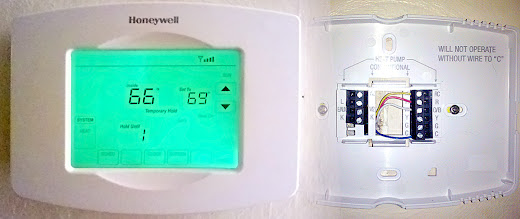
The thermostat I was replacing only controls my gas fired, hot water boiler which provides heat only. I didn't have to worry about cooling as my AC unit runs off a separate thermostat. There were three wires coming out of the wall where my old thermostat was mounted. My heating system only requires two wires, R and W, to operate. I thought I could use the third wire to power my thermostat and use that as the C wire. Unfortunately I ran into a couple of problems.
First, there wiring was very old and there appeared to be a break in that third wire. I couldn't get current to flow to it from the basement.
Second, and probably most importantly, I called the manufacturer of my boiler to double check that it would be okay to connect the thermostat to the C terminal on the 24 volt AC transformer in the boiler. These types of thermostats are called "power stealing" thermostats and the manufacturer (Weil McLain) does not recommend using a power stealing thermostat with my boiler. They were worried that the additional load from the thermostat may cause the transformer to prematurely burn out. They recommend using a separate 24 vac transformer to power the thermostat.
The instructions for the Honeywell Wi-Fi Programmable Touchscreen Thermostat (RTH8580WF1007/U)
 I was installing didn't specify how to hook up an external power supply to the thermostat but calling customer service I was able to find out how to attach an external transformer. If your thermostat is also controlling your cooling system or you have a different type of heating system the configuration might be different. It's a good idea to call the manufacturer of your thermostat and get specific instructions for your model and HVAC unit.
Update: wi-fi on the thermostat sucks. You can only update the thermostat provided the thermostat can connect to the internet. Hurricane Sandy caused me to lose my home internet but I still had power and heat. When I went to bed the following night I was chilled do the bone having been outside most of the day dealing with the aftermath and i wanted to turn up the heat without getting out of bed but i couldn't because my internet was down. I could access all other wired and wireless devices on my network, just no internet access. There is no way to connect to the thermostat directly. It is all done through Honeywell's cloud service which it turns out collects my homes temperature readings and heating system information every 12 seconds. I don't like that and i don't like not being able to access the thermostat from home when my internet is down.
Change Your Thermostat Before It Gets Cold
With any project things can go wrong. You don't want to be in a position where it's the coldest part of winter and you're without heat for whatever reason!
Also check with your HVAC system manufacturer and thermostat manufacturer for specifics about your installation. Check with all applicable local building codes.
If snaking wire through walls and making electrical connections is not something you're comfortable with call an electrician.
What You'll Need
Materials
- New Thermostat (I used a Honeywell RTH8580WF)
- 24 Volt AC plug-in transformer (I used an MGT-2440
)
- 18 gauge thermostat wire. Number of conductors should be at least the amount of wires coming up from your HVAC system + 2 for the transformer. I needed a total of 4 conductors so I purchased the Southwire 50 ft. 18/2-Gauge Thermostat Wire 64162179
. You may need more or less depending on how far you have to run the wire.
- 4 Wire nuts (one for each conductor you'll be using). Small ones, yellow or orange should do it.
- Fire Block Sealant
- Electrical tape.
Tools
- Needle nose pliers with wire cutter
- Wire stripper (if you're not comfortable stripping wire with a wire cutter)
- Philips head screwdriver
- Precision flat-head screwdriver (Like from the Stanley 66-039 6-Piece Jewelers Precision Screwdriver Set
)
- Fish Tape (I used Gardner Bender EFT-21PN 25-Foot Cable Snake Steel Fish Tape
)
- Caulking Gun
Step 1: Plan Your Wiring
I could have continued to use the 2 thermostat wires that were in my wall plus add 2 more wires that will run outside the wall to a nearby outlet where I would plug in the 24vac transformer. I didn't like this setup because I didn't want the wire to the transformer exposed where the thermostat was mounted. The installation would look much cleaner if all the wiring ran through the wall as it did previously.I needed 4 conductors. Two from the boiler and 2 from the 24vac transformer. The closest wire I could find was 5 conductor thermostat wire which is what I used. I was going to run the 5 conductor wire from my thermostat down to my basement and then I'd splice 2 more cables in the basement. One set of 2 conductors going to the boiler and two more going to the transformer which will be plugged into a wall. I used the same 5 conductor wire throughout (except for the connection between the boiler and new wire where I used the existing 3 conductor wire).

There is no standard color coding for thermostat wiring. I decided to use the following convention. R - Red, W - White, Rc - Yellow, C - Blue. The yellow and blue wires will go to the transformer and since it's an AC transformer they could be switched.
The 5 conductor wire will be snaked down the wall into my basement. From there I'll separate it into two runs. The Red and White will connect to an existing wire in my basement that goes into my boiler and connects to the R and W terminals on my boiler. The Yellow and Blue wires will run along another wire that goes to the plug-in 24vac transformer that will be plugged into a nearby outlet in the basement.
Step 2: Turn Off Your HVAC System
Before doing anything turn off the power to your HVAC system. This will vary by system but there should be some sort of switch near your system or there might be a breaker specifically labeled in your main circuit breaker panel.Step 3: Remove Old Thermostat
Your new thermostat will come with instructions and wire labels. Follow the instructions to label your existing wires with the stickers so you know which wire is which.
After you label your wires but before you completely disconnect them from the old thermostat, wrap a pencil around the existing wires and/or tape the wires to the wall the prevent them from slipping down into the hole.
If you need to drill holes for new wall anchors to screw in your new thermostat, do that now. Luckily I was replacing a different Honeywell Programmable thermostat that used the same hole spacing.
Step 4: Run New Thermostat Wire
This is the tricky part and how you run your wire is going to depend on how your existing wire is run. I was lucky and my thermostat had a straight run down the wall it was installed on down to my basement. By pulling on the wire from upstairs and down in the basement I was able to tell that the wire was not firmly stapled to the wall and I'd be able to pull it right out. The types of fasteners I saw used in the basement were fairly loose fitting. If that's not the case for you you might have a harder time snaking the new wire. You might have to make small holes in your walls here or there. Fishing wire can be tricky and you might want to hire an electrician to do this for you. Remember, it's best not to try and tackle this when it's very cold and you don't want to be without heat for a couple of days if something goes wrong.
Prepare Fish Tape
The first time I ever used the GB Fish Tape it was very difficult to get it out of the reel. You're supposed to pull the steel tape out by hand. It's coated in oil which makes it tricky. I took the tape outdoors, don't do this on carpet or the oil will stain it, and pulled out as much of the tape as I could by hand. Then I stepped on the end and pulled on the reel slowly working all the tape out. As my reach wasn't sufficient I walked down the tape to change where I was putting pressure. Be careful not to severely bend the steel tape when doing this. One I got all the tape out I reeled it in and repeated the processes. Now whenever I use the fish tape it comes out effortlessly.
Attach Wire to Fish Tape
From upstairs, where the old wire was coming out of the hole in the wall I attached the wire to the end of the fish tape. There's a small hole in the end that I passed the wires through and then used electrical tape to secure everything together. Make sure that the tape is put on neatly so that the point of connection isn't significantly thicker than the thickness of the wire. Tug on it a few times to make sure the wire isn't going to come off of the fish tape while you're pulling it through the wall.
Make sure you have enough fish tape unreeled to reach down to the other end of the opening.
Pull Wire Down
Next I went down to my basement where the old thermostat wire was coming out of the floor boards. I carefully pulled down on the old wire until the fish tape came down to a working level. I had to run up once to feed in the fish tape when it seemed to get a big snagged. This operation is easier if you have one person guiding the tape down from above and another pulling from below but is doable with one person.
Attach New Wire To Fish Tape

First I unspooled a sufficient length of wire and straightened it out a bit. I made sure to unspool enough wire that when I pulled the end upstairs the spool will still be on the ground so that the weight of the spool wouldn't pull the wire back down.
I stripped off about 1.5" of the brown outer wire wrap exposing the 5 individual colored wires. I passed those wires through the holes in the end of the fish tape. Then I took 3 of the individual strands one by one and wrapped them around the tip of the fish tape. Two in one direction and the other in the other direction. This will help secure the wires on the tape. Finally I securely wrapped the connection using electrical tape and tugged on it a few times to make sure it wouldn't come apart while pulling the wire through the wall.
I had taken a picture before I wrapped the connection with electrical tape to show you how I fastened the wire to the end of the tape. Unfortunately I didn't realize the photo didn't come out when I took it. The description above will hopefully be sufficient. Any way you attach it it's important that it provides some security and doesn't add much to the width.
Pull New Wire Up Through Wall
The first step is to start feeding the wire up from below until the connection between the fish tape and thermostat wire is past the hole. This is one of the points where the wire might snag. It's easier to do this with two people but I managed on my own.
Once the connection was through I double checked that the wire was straight and that there was enough unspooled.
Then I went upstairs and carefully pulled the fish tape up until the new wire came out of the hole in the wall.

I made sure I had enough wire to work with and I wrapped some tape around the new wire, while keeping the tape on the spool, to prevent the wire from slipping back down the hole. You could also wrap the wires around something like a pencil.

Step 5: Connect Wires to Thermostat Base Plate
With the new wire fished through the wall it was time to start wiring up the new thermostat. I trimmed the wire to an appropriate length so about 4 inches was sticking out of the wall. I'd deal with the mess of unwrapping the electrical tape off the end and fish tape later. I began by stripping a couple of inches of the brown outer wire sheath to expose the 5 individual color coded wires within. Then I wrapped the Green wire back against the main wire bundle since I wasn't going to be using it then I stripped about 3/8" off the end of the 4 remaining wires as shown.

Remove Jumper
The base plate of the thermostat comes with a metal jumper connected between Rc and R, it looks like a small staple. This jumper needs to be removed to be able to wire the thermostat to an independent power transformer. To remove it, use the small flat-headed precision screwdriver to loosen the two screws for Rc and R in the black terminal block. You don't need to unscrew them all the way, just until the tops of the screws are flush with the top of the black terminal block. Once both screws are loosened just pull the jumper out.
The Rc terminal is used for connecting the cooling relay. If your thermostat controls both your heating and cooling system I'm not sure how you'd go about wiring an external transformer. In that case you'd likely need to wire your thermostat's C wire directly to the transformer on your 24 volt HVAC system.
Attach Wires
One by one feed the end of each wire into it's appropriate terminal block and screw it down to hold it in place. The convention I'm using is:
- R - Red (to boiler)
- W - White (to boiler)
- Rc - Yellow (to transformer)
- C - Blue (to transformer)
Once the wires are attached you can secure the base plate to the wall. I used a small level on the side to make sure the base was mounted straight. (The top of the thermostat and base plate are curved.) The picture, didn't come out quite as straight :) but you can see how the 4 wires attach to the thermostat's base plate.

Depending on your HVAC system your wiring might be different.
Step 6: Connect Thermostat To Transformer
 Back down in the basement and I ran the new wire to where the connection point to the wiring that goes to the furnace is. I think when they installed my new boiler they spliced in a new thermostat wire into the old one and the connection point is on a wall above the boiler. I ran the new wire to that point, gave my self a little extra to work with in case there where any mistakes and I cut the wire and stapled it securely to the wall.
 I then stripped off about 2" of the brown outer wire sheath. As before I wrapped the green wire back around the main wire since I wasn't going to be using it. Then I stripped off about 3/4" from the ends of the 4 remaining wires.
Next I determined where I was going to plug the 24 vac transformer in and measured out the appropriate length of wire from the spool. I knew I was going to have extra thermostat wire left over and I will be using that instead of getting a different 2 conductor wire since I won't need all 5 for this run.
After trimming the wire to length, I stripped off the ends of the wires and, wrapped the each around one of the 2 screw terminals on the transformer and tightened them down. The position of these two wires isn't important as this is an AC transformer. I picked this particular 24vac transformer (MGT2440) because it had the screw terminals.
Next I attached the yellow wire coming from the transformer to the yellow wire running down from the thermostat. I stripped the ends of both about 3/4", used pliers to wrap the wires around each other in a clockwise direction and secured them with an orange wire nut. I repeated the process for the blue wire from the transformer to the thermostat wire.
Before going any further I wanted to make sure the thermostat was getting power so I plugged the transformer in, ran upstairs, pushed the thermostat onto it's base and was happy to see the screen on :)

I had already configured to wireless settings when I was testing the 24vac transformer before I went through all this trouble.
Step 7: Connect Thermostat to Boiler
There was a 3 conductor wire running from the boiler to the old wiring for the thermostat. Luckily this new wiring was color coded so I knew which colors went to the R and W terminals on the boiler. One by one I attached the Red wire from the new wire that I ran from the thermostat to the basement by stripping off 3/4" off the new wire and wrapping it around the wire running to the thermostat R terminal in the boiler. The boiler wire was previously connected to the old wire and already stripped. I capped the connection with a wire nut and repeated the process for the White wire to the wire that runs to the W terminal on the boiler.
I flipped the switch to turn the power to the boiler back on and ran upstairs to make sure everything was working. I turned up the thermostat and checked to make sure the boiler fired up. While downstairs next to the boiler I used my phone to turn the thermostat down and within a few seconds the boiler turned off. :)
Step 8: Wrap Things Up
Now that I know everything is working correctly I wrapped electrical tape around the wire nuts to help keep them secure and I used the Fire Block Caulking in the opening from the basement up to the wall where the new thermostat wire runs. To be on the safe side I double checked that everything was working. Using the app on my phone I can adjust the thermostat from anywhere.
One of the nice things about having the thermostat plugged into the wall is that the light on the thermostat can always stay on and I don't have to worry about batteries draining. The thermostat is next to an opening I tend to bump into when I go down to grab a glass of water in the middle of the night. Hopefully no more stubbed toes and I never have to worry about replacing the batteries.

Better Box Fan Air Purifier

A better more efficient and odor eliminating homemade air purifier than just taping a 20x20x1 filter to a box fan. Sometimes you need to help clear the air in a dirty environment but don't want to use an expensive air purifier such as in a room after renovating and painting. Here's a cheap and easy way to build one.
Air purifiers can be expensive and you've probably seen articles recommending to just put a 20" x 20" x 1" furnace filter on a cheap 20" box fan and POOF! instant cleaner air for not a lot of money. It really does clean the air pretty cheap.
There's a problem with this though. These fans weren't designed to be run with a filter. The filter will restrict air flow which will put a higher strain on the motor causing it to use more electricity and in worse cases could be a fire hazard. The higher the MERV rating (cleaning efficiency) of the filter the more stress it will put on the fan.
Don't worry! You can still have your cheap air purifier as long as the filter area is increased to decrease the effect of air resistance. Instead of using one 20x20x1 filter we'll use two 20x25x1 filters which increases the filter surface area over 250%. It's a little more expensive because you're using two filters instead of one but the increased filter surface area also helps the filter last longer before it gets clogged up and we're saving on energy use compared to a single filter.
I can't take credit for the design, I found it via Marshall Hansen Design but I'm using different filters.
I recently remodeled my basement and there's a lot of dust (including drywall dust and sawdust) and fumes from paint, cleaners and other building materials. It's an underground basement and mold has to always be a conern too. Because part of the space will be my home theater in the future I plan to get a more expensive air purifier that's smaller and quieter such as this Fellowes Quiet Air Purifier AP-300PH with True HEPA Filter
 because it has great reviews, is reasonably priced and the replacement filters aren't that expensive or a Sharp Plasmacluster True HEPA Air Purifier
 or Blueair HepaSilent Air-Purification System
 if I find some extra Benjamins in the couch cushions. But I don't want to put that in the dusty environment right away because I'll have to replace the more expensive filters fairly quickly because the air is so bad. I also don't want to spend the money right now but I do want cleaner air now.
So I decided to get things going with a homemade air purifier that has filters that not only clean the air of particulates but also reduce VOCs and odors. Even after I purchase an air purifier I'll still have an air purifier I can use for other purposes like when I'm painting or cutting wood.
Also, don't forget to add more plants to your home. They're natures air purifiers. Not only do they convert carbon dioxide to oxygen but houseplants filter toxins and emit negative ions too!
What You'll Need
Materials
- Filtrete Home Odor Reduction Filter, 20-Inch by 25-Inch by 1-Inch, 4-Pack
(only using 2 at a time)
- 20" Box Fan
- Cardboard (from the package the filters came in) or oak tag
- Duct Tape or Clear Cellophane Tape
- Optional Plug-in Timer
so the fan isn't running constantly without manual intervention.

Tools
- A pair of scissors or utility knife
Quick Info About Filters
The nice thing about this box fan filter setup is you can use any filters you want. If you are only concerned about large particles generated from something like cutting wood, you can use cheaper, lower MERV rated filters. If you're worried about finer particles from allergens such as mold, you can use a higher MERV rated filter. To understand more about what the MERV ratings mean have a look at Table 2 on this EPA article on residential air.
I chose to go with the Filtrete Home Odor Reduction Filters which are a new type of filter from Filtrete. They contain a lot of activated carbon to help filter out odors and VOCs. They are rated MERV 11 and are equivalent to their 1000 MPR furnace filters. They should do a good job with even the fine drywall dust and the activated carbon will help a lot with odors. I bought a 4 pack for around $57 which gives me 2 sets of filters.
 |
| Filtrete Odor Reducing Air Filters |
 I've been using in my air conditioning for the past few years. Plus Filtrete packs over 180 grams of activated carbon to help reduce odors.
After I go through both sets of carbon filters I'm probably going to switch to the Filtrete Elite Allergen Reduction Filter
 which does a much better job of filtering small particles. If odors are a problem I'll get some Cut-to-fit Carbon Prefilters
 and tape them over top of the Filtrete filters.
Okay, enough of the why, now for the how!
Step 1: Unbox The Filters
You're thinking "OMG! He's actually describing how to open a cardboard box?!?!?!" The best deal I found for these filters were on Amazon and with my Prime membership (or supersaver shipping) the shipping is free. Plus the packing box is going to be part of the filter so we need to keep in intact.The box is sealed very well. Not only is it taped but the seams are also glued together. To get the filters out of the box I cut the top where it's perforated with a utility knife as shown.

Be careful not to cut too deep and damage the filters. Keep the box someplace safe to the side while we continue.
Step 2: Hinge Filters
Start by taking 2 of the filters out of their plastic wrappers and lay them one on top of the other with the air flow arrows pointing towards each other. With the Odor Reducing Fitlers this means the black, carbon sides will be facing each other.

With the filters lined up, tape one of the short (20") edges of the filters to create a hinge between the two filters as shown.

I decided to go with white duck tape so it looks a little nicer but it makes it hard to see in the photos against the white cardboard filter frame.

With the filters lined up, tape one of the short (20") edges of the filters to create a hinge between the two filters as shown.

I decided to go with white duck tape so it looks a little nicer but it makes it hard to see in the photos against the white cardboard filter frame.
Step 3: Tape Filters To Fan
Lay the box fan face down on a flat surface to mount the filters to the back making sure the bottom of the filters are about flush with the bottom of the fan and do not extend past the bottom.

Use a strip of duck tape to secure each side to the side of the fan.


Use a strip of duck tape to secure each side to the side of the fan.

Step 4: Cut and Attach the Cardboard
Cut out one of the large sides of from the cardboard shipping box, place it over the top of the of the filters and secure it with a strip of tape to the top of the fan. Position it so that it's pretty even over both filters but it doesn't have to be perfect.

Using a pencil, trace around the filters (while pressing down the cardboard so nothing moves) to mark where the cardboard needs to be cut.
Lift the cardboard up (the front piece of tape acts like a hinge) and cut along the lines to trim the sides. By the way, I really like these Fiskars Cuts+More 5-in-1 Multi-Purpose Scissors .
.

Repeat the process for the bottom cardboard. The other large piece from the box is seamed but it's taped and glued and very stiff so it shouldn't be an issue but you can run a strip of duck tape over the seem if it makes you feel better.
Also keep in mind that the bottom of the fan has feet. I positioned the cardboard underneath the feet and then pulled the feet out to tape.

After taping up the sides of the bottom cover to the filters, I added an extra strip of duck tape all the way around where the filters/cardboard meets the fan for added support. The rounded corners of the fan means there might still be an air gap there so check them and add extra duck tape if necessary. On the bottom there are also some holes, duck tape over those as well. Finally, replace the feet.


Using a pencil, trace around the filters (while pressing down the cardboard so nothing moves) to mark where the cardboard needs to be cut.
Lift the cardboard up (the front piece of tape acts like a hinge) and cut along the lines to trim the sides. By the way, I really like these Fiskars Cuts+More 5-in-1 Multi-Purpose Scissors
.
Repeat the process for the bottom cardboard. The other large piece from the box is seamed but it's taped and glued and very stiff so it shouldn't be an issue but you can run a strip of duck tape over the seem if it makes you feel better.
Also keep in mind that the bottom of the fan has feet. I positioned the cardboard underneath the feet and then pulled the feet out to tape.

After taping up the sides of the bottom cover to the filters, I added an extra strip of duck tape all the way around where the filters/cardboard meets the fan for added support. The rounded corners of the fan means there might still be an air gap there so check them and add extra duck tape if necessary. On the bottom there are also some holes, duck tape over those as well. Finally, replace the feet.
Step 5: Seal The Back
Where the hinged filters meet the cardboard in the back, add another strip of duck tape for support and to seal any gaps.

Give another look around the seams to make sure there aren't any gaps. If you find any, tape them up.
When using the fan, I always make sure that the cord isn't underneath the cardboard and instead is under the metal fan chassis, just in case something goes wrong and the cord overheats. Can never be too safe.
Replacing Filters
When it's time to replace filters, use a utility knife to cut the filters free but leave the cardboard in place. Then just hinge and attach the new filters.
DIY Small Closet Organizer Plans

Free woodworking plans for a DIY small closet organizer for closets 3-5' wide.

Lack of shelf space tends to be the reason closets get so cluttered in the first place. We tend to use closets for more than just clothes. Anything that we don't want to throw away yet don't want out in the open gets thrown in the closet where it tends to get forgotten. If you haven't seen your closet floor in ages because it's pilled high with bags, boxes and shoes, that's a clear indication you lack enough shelf area in your closet. This closet organizer design aims to fix that problem.
Dimensions
Use these plans as a guide and customize them to your needs. The plans should work well for reach in closets between 3' to 5' wide and 24" deep. If your closet is larger, see my Closet Organizer Plan for 5' - 8' closets. If this seems like too much work check out my Easy Small Closet Organizer Plans.
In this example we're using a 48" wide by 24" deep reach-in closet that has an 11" space between the left side wall and the door trim. Make any necessary adjustments to suit your closet. Here is the floor plan of the closet we'll be working in.

If you're closet doesn't have much space between the sidewall and the door trim you won't be able to include the extended lower shoe shelves. You can still include the shoe shelves but they will only be 15" deep like the other shelves.

If you're closet doesn't have much space between the sidewall and the door trim you won't be able to include the extended lower shoe shelves. You can still include the shoe shelves but they will only be 15" deep like the other shelves.
What You'll Need

Materials
- (1) 4' x 8' sheet of 3/4" hardwood veneer plywood
- (1) 2' x 4' sheet of 3/4" hardwood veneer plywood
- about 32' of edgebanding
- (2) 8' 1x4 boards for main supports (match plywood species)
- (4) 8' 1x2 or 1x3 boards of shelf supports
- (1) Knape Vogt 96in Oval Tubing Chrome
- (2) pairs of Knape & Vogt Open Flange For 880 Tube Chrome
- (4) L brackets
- (32) Kreg SML-C125-100 1-1/4-Inch Coarse Washer-Head Pocket Screws
- 1-1/2" flat head wood screws for attaching plywood to supports
- 3-1/2" wood screws for attaching supports to studs


Tools
- Table saw, or circular saw with guide to cut plywood
- Miter saw or miter box to cut boards
- Kreg Pocket Hole Jig
- Drill
- Pilot hole/counter sink bits
- Level
- Tape measure
- Pencil
- Iron
- Utility knife or edgebanding trimmer
Cut List
- (1) 48" x 24" 3/4" Plywood Top Shelf
- (1) 82-1/2" x 15" 3/4" Plywood Main Divider
- (1) 42 x 15" 3/4" Plywood Lower Cabinet Side
- (1) 24-1/4" x 15" 3/4" Plywood Lower Cabinet Top
- (4) 15" x 15" 3/4" Plywood Shelves
- (3) 15" x 24" 3/4" Plywood Shoe Shelves
- Assorted 1x4 boards for main supports
- Assorted 1x2 or 1x3 lengths for shelf supports
Cut Plan
The size of your closet will most likely be different so double check the cut plan after you make the necessary adjustments to the component dimensions.
3/4" Plywood
The main parts of the closet organizer are cut from 3/4" hardwood veneer plywood. Two sheets where used for this plan, 1 full 4' x 8' sheet and one 2' x 4' quarter sheet.

Some of the cutoffs can be used for the 2" shelf supports but you might find it easier to use 1x2 or 1x3 boards that match the species of plywood you selected instead. It will save time in making all those little cuts and edgebanding.
1x4 Boards
The 1x4 boards are used for the top support as well as the lower support. The species of wood should match the plywood you selected and be finished the same way. You'll need 2 8' boards. Cut plan is not included because it will depend on your closet dimensions.
1x2 or 1x3 Boards
There isn't enough scrap on the plywood to create enough supports for the sweater and shoe shelves on the left of the organizer. You may want to forego the plywood supports and just use boards instead to minimize the cuts in plywood which can be time consuming if you don't have a table saw. Using boards also means you won't have to edgeband the supports that will be visible.
If you're using boards for all the shelf supports you'll need 4 8' boards.
Step 1: Cut and Finish Parts
It's best to cut out all the parts and finish them before installing the closet organizer. Make any adjustments necessary to suit your closet size, cut out the parts, apply edgebanding to the edges that will be visible, sand smooth with 80 then 120 grit sand paper, finally either prime and paint them or stain and seal them.
Oil based paints and finishes are not a good idea for closets because they can out gas for a long time and make your clothes smell. Instead use low VOC water based paints or water based stain and a water based finish such as Minwax Water-Based Polycrylic.
Step 2: Prepare Your Closet
While your waiting for the closet organizer components to fully cure, get your closet ready for the new organizer.
Empty out the closet and store your clothes in a safe place. Carefully remove the old closet shelf, rod and other boards that were a part of that configuration.
Patch the walls with joint compound, sand and then prime and paint with a low VOC water based paint.
Step 3: Mark For Top Support
Use a level to find the highest point in the closet floor along the back wall. Houses can shift over time and the floors won't always be level.
From the high point in the floor measure up 82-1/2" and draw a level line (in pencil) on the back wall, both side walls, and the front section where the shelves will be.

Please note that to make it easy to show the installation, some of the walls are not visible.
Step 4: Install Top Support
Measure and cut the 1x4 top support and screw it into the walls using 3-1/2" wood screws making sure to screw into the studs. The top of the board should align with the level line drawn in the previous step.
Install the supports in the order shown. Starting with the return wall, next the left side wall, the right side wall and finally the back wall. Check your stud locations on the right wall and cut that support long enough to be screwed into at least 2 studs, one in the corner, one towards the end.

Drive 2 screws at each stud location.
Step 5: Install Divider
Draw a plumb line using a level 15" from the left wall (the wall where the shelves will be.)

Prepare the divider by cutting a notch at the top to fit around the top support 1x4 and at the bottom to fit around the baseboards.
Drill 2 pocket holes at the top notch to be able to attach it to the top support.

Align the left side of the Divider with the plumb line and drive 2 screws through the top pocket holes. At the bottom use an L bracket to attach the divider to the floor, making sure it stays plumb.
Step 6: Install Lower Support
Draw a level line on the right side of the Divider, 42" up from the floor. Install the Lower Support 1x4 so the top is flush with the level line. Use 3-1/2" wood screws to secure the Lower Support into studs. Make sure that when you install the Lower Support you to not push the Main Divider out of plumb.

Secure the main divider to the end of the lower support using 2 1-1/2" wood screws. Drill pilot holes before driving the screws to prevent splitting.

Step 7: Assemble Lower Cabinet
The lower cabinet defines the bottom hanging area. It consists of the top and side and gets attached to the main divider.
Begin by drilling the necessary pocket holes in both pieces. In the Lower Cabinet Top there are 3 pocket holes on the side to attach to the main divider. In the Lower Cabinet Side there are 6 pocket holes. 3 on the top to attach to the Lower Cabinet Top, and 3 on the bottom to attach to the floor. You can also use an L-Bracket to attach the side to the floor instead.
After you drill the pocket holes, attach using the appropriate pocket screws as shown below.

Step 8: Install Lower Cabinet
Position the assembled Lower Cabinet over the Lower Support as shown. You'll need to cut a notch on the bottom of the Lower Cabinet Side to fit around your baseboards.

Make sure it's level and plumb all around and secure it to the Main Divider using pocket screws, to the Lower Support from the top and side using 1-1/2" wood screws that are countersunk (drill pilot holes to avoid splitting), and finally to the floor using pocket screws or L brackets.
Step 9: Install Top Shelf
Check to make sure the Top Shelf fits properly. Trim it to size if necessary then place it so it rests on the top supports.
Screw it in place using 1-1/2" wood screws that are predrilled and countersunk. Screw it down into the top supports as well as the top of the Main Divider.

Step 10: Install Closet Rods
Mount the Closet Rod Flanges, cut the pole to size using a hacksaw and mount them as shown.

The closet rods should be installed so that the top-center of the closet rod is 12" away from the back wall (not the back support) and 1-1/2" down from the shelf above it.

Step 11: Install Shelf Supports
Mark out level lines on the walls where the shelves will be installed. You can space the shelves whichever way works for you. A good starting point is about 12" spacing for sweater shelves and about 7" spacing for shoe shelves.
Use 3-1/2" wood screws driven into studs to install 2" strips of plywood (or 1x2 or 1x3 boards) at the marked lines to support the shelves as shown.

Step 12: Install the Shelves
Place the shelves on the shelve supports. Trim to size if necessary. Attach the shelves to the shelf supports by screwing down from the top with 1-1/2" wood screws that are pre-drilled and countersunk. On the side where the shelf meets the divider attach the shelf to the divider using pocket hole screws as shown.

For the lower shoe shelves that extend to the front wall, you'll need to mark and cut out an angle from the cabinet to behind the door molding.
Your closet organizer is now complete and ready for your clothes.

Subscribe to:
Posts (Atom)